Reducing carbon emissions with new green power technology
1 . . . By promoting the maximum use of wind energy and by introducing a new VAWT concept, which dramatically increases the potential for scaling up the harvesting of wind energy from the current maximum of 15 MW to a massive 375 MW per machine while minimising carbon emissions and energy production costs by dramatic increases in efficiency. The annual output from each VAWTs being as much as a traditional wind farm rated at 468 MW. That will make it have the lowest CO2 footprint of all energy production systems.

2 . . .To also seek your help to convert the idea, which is not limited by current design constraints, into reality to make a massive impact on reducing CO2 emissions:-
Everyone can do something. . . . This planet is our home and our children’s future. What legacy do you wish to leave? There is a link to ” How you can help” at the bottom of this page
If you have any doubts as to why you should be concerned with our climate listen to Greta Thunberg https://www.youtube.com/watch?v=bW3IQ-ke43w — Then click back to return to this site.
UK patent has now been granted ref: GB2581622
Most scientists acknowledge that it is vital for us all to reduce carbon emissions. By comparing the emissions for different methods of electric energy production it becomes apparent that there is a vital need for even better wind turbines. They need to be capable of being deployed at sea and their capacity needs to be scaled up dramatically. The Demand for electrical energy is expected to increase 3 fold by 2050 so it is not enough to increase the supply via renewable energy. The use of any combustion processes to generate electricity, which has up to a 200x bigger carbon footprint compared to wind powered generation, must be replaced worldwide.
CO2 in Energy Production
* * * * Click here * * * * for the link to see details on how electrical energy is produced.
Why the novel turbine design ( a very big vertical axis turbine) is needed. Compare the CO2 levels
You can skip down to the design concept further down the page, or to more fully understand the technical benefits of the new concept and the limitations of current horizontal axis wind turbines (HAWTs) and vertical axis wind turbines (VAWTs) can be explored by looking at how they work.
To look at the limitations of and how horizontal axis wind turbines ( HAWT) work, click on the image below.

For all wind turbines it is the lift and drag forces due to the apparent wind at an angle of attack (AOA) to the aerofoils that is relevant. For simplicity a similar cross section is shown and the axis of rotation are not shown. The Savonius turbines (drag type VAWT) are not included. They are simple but not as efficient as aerofoil based turbines.
To look at the limitations of and how vertical axis wind turbines (VAWT) work, click on the image below.
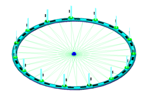
Introducing the new concept, which is not limited by current design constraints. It can be scaled up massively and that enables energy to be stored kinetically (flywheel effect). It is a flywheel, which is driven by the wind.
It is only possible to integrate a large flywheel for energy storage and wind energy harvesting by using a substantially vertical axis of rotation, so it is also a VAWT. At large scales it is not practical to use support arms so it is desirable to float the entire system and use the water as part of the flywheel.
As the water is part of the energy store, it is best if this is quite deep. There is a trade off between the time it takes to get the system up to speed with the amount of energy stored depending on depth of water. The steady state drag on the system is relatively low. It is found by using Couette flow analysis.
Some of the wind energy is used to maintain the kinetically stored energy ( the steady state drag above) as like any form of battery some is lost, but this amount is relatively minimal.
The kinetic energy stored is increased, by speeding up, when the net wind energy harvested is greater than the generators capacity. Similarly kinetic energy is released, by slowing down, when converting power when the net wind energy drops below the threshold for generation at that power level.
This energy buffering capability dramatically increase energy production compared to any other wind turbine. This is of particular benefit where the wind velocity varies significantly. The more frequent the changes in wind velocity the greater the benefit of this energy buffering feature.
To look at details of how the new concept works click on the image below.
The advantages of using large diameters to increase the flywheel effect also has aerodynamic advantages
1. . . The curvature of the path of the aerofoil through the air is dramatically reduced enabling better performance from symmetrical aerofoil sections.
2. . . For a given tip speed ratio the bigger a diameter is the slower the changes in direction, resulting in the closer to steady state of the apparent wind to the aerofoils. This makes it much easier to adjust the angle of the aerofoil to maintain the required Angle of Attack. The opposite is also true . . . . . . The smaller the diameter the faster changes in direction occur. . . . .momentum becomes more relevant and it becomes much more difficult to maintain the required angle of attack with the preferred approach, which uses aerodynamic balance with a canard controlled system.
3. . . The bigger the diameter the bigger the circumference enabling more aerofoils to be mounted at a required minimum pitch for a designed tip speed ratio, resulting in more torque and greater power.
4. . . The bigger a system the bigger the chord of the aerofoil can be. This increases efficiency because the Reynolds number is raised resulting in greater lift forces per unit surface area of the aerofoil section.
5 . . . The bigger the chord the stronger the aerofoil can be resulting in taller aerofoils with greater lift forces due to greater surface area.
6 . . . Using diameter to aerofoil height ratios of 8+ spaces the leeward and windward aerofoils are then at a similar distance to that recommended for current HAWTs wind farms. This results (proportionally to swept area) in greater energy harvesting on the leeward side than VAWT systems with low diameter to height ratios.
For the offshore version: The ring which supports the aerofoils can be a skeletal structure, made in sections and of neutral buoyancy, mainly several metres below the water line with ” conning towers / floats ” above water and on which the aerofoils are mounted to ensure they are well clear of any storm / freak waves. This achieves 3 things: (1) Boat access to the generating hub. (2) Very little stress on the support structure due to waves as most is below the water. (3) The support structure and the links to the hub create a friction link to the water. The structure and the water become a giant flywheel of millions of tonnes storing multi GWh of energy. As with any battery / flywheel there are losses but Couette flow analysis indicates that this is relatively minimal.
In addition to the above Posts are added to reflect any alternatives or developments of the concept.
Below is a video of a micro model in a very simplified format, without a flywheel. The sole purpose of the model was to demonstrate how the canards can control the angle of attack of the aerofoils. It does shows how aerofoils can rotate freely about their own axis, ( a feature that is essential to enable full feathering during maintenance for any large scale system operating in adverse conditions ). It also shows how stays can be used to support aerofoils of virtually any height. The model demonstrates that it is possible to have pitch control with feathering capability without an electrical control system.
The control system , which uses cams and a canard is designed for large diameter VAWTs where a simple system (not included in the model) to advance and retard the pitch control cams by a few degrees, dependent only on whether the apparent wind is on the windward or leeward side, enhances the system by pitching the canard to optimise the angle of attack of the aerofoils for all azimuthal positions resulting in maximum energy harvesting capability.
Original power production comparisons were made based on the new VAWT concept rated at 240MW with a wind speed of 11m/s using a (conservative) generic coefficient of performance of 0.4 and an enhanced HAWT farm using 20 turbines each rated at 12MW at the same wind speed. This comparison is in terms of absolute power generated and power generated per surface area used for wind farms. These comparisons are based on an example of wind speed probability. Even allowing for losses of stored kinetic energy it shows a massive potential for increased energy production using the new concept. It even shows that with kinetic energy buffering it is possible to generate more power overall with smaller generators using the new VAWT concept compared to turbines which do not have this feature.
Following the use of QBlade, as advised by Sandia National Laboratories, to check lift and drag coefficients and enable the running of a simulation. It was found that the giant VAWT could produce 300 MW in 11 m/s winds at a tip speed ratio (TSR) as low as 2. The power curve shows over 300 MW between TSRs of 2 and 4.5 peaking at 375 MW at a TSR of 3.
So now it is valid to compare the peak power of a single VAWT to 25 HAWTs each rated at 15 MW and due to the flywheel effect the total annual power generated will be a lot more. With a generator based on peak power of 375 Mw and the flywheel effect the annual output could be similar to that of a traditional wind farm rated at 468MW. That is equal to 31 HAWTs rated at 15 MW each.
To look at the details of the original power generation comparisons click on the image (part of a HAWT wind farm) below

If you have gone though the links above you will now know that this novel approach could provide the means of producing energy with the lowest carbon emissions. PV is a good renewable energy system but comparing the CO2 footprint of this giant VAWT approach to PV for global power generation represents a CO2 saving of 720 million tonnes. This planet is our home and our children’s future. What legacy do you wish to leave?
. . . . . To see how you can help * * * * Please click here
you are welcome to leave questions and comments and suggestions but only relevant technical information will be posted onto this site after moderation.
To protect privacy all comments will be treated as private and no comment will be published until after moderation and then only if it starts with a request for publication and is written in English. No adverts will be published

